Estimating aid only. Results are estimates, provided without warranty, and must be verified against applicable codes (NFPA 54, SMACNA, ASHRAE) and the engineer of record before use in any installation, bid, or permit submission.

Helm Tools — duct and pipe sizing calculators

Duct sizing

Current Options

Current Options

Current Options

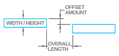
Diagram of a one-piece offset duct: Width/Height is the duct dimension, Overall Length is measured along the run, and Offset Amount is the perpendicular distance between the inlet and outlet ducts.

Enter width, overall length, and offset to get the cut angle, duct piece length, and trim amount.
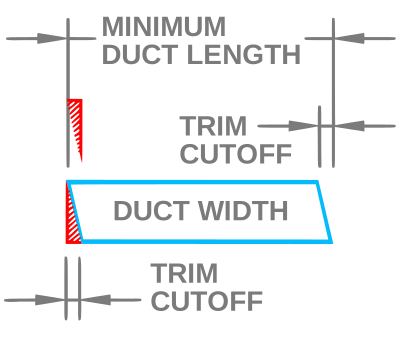
Result diagram of the offset piece showing the cut angle, the duct piece length, and the trim cutoff removed from one end.
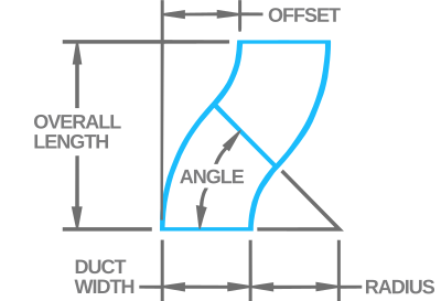
Diagram of a double-elbow offset: two equal-angle radius elbows joined to shift the duct by the offset amount over the overall length.

Two equal-angle radius elbows. Enter duct width (required) plus any optional targets to filter results.
Angle range to search
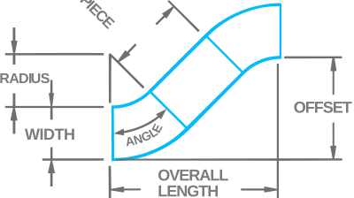
Diagram of a three-piece offset: two oblique slant pieces joined by a straight center connector, shifting the duct by the offset amount.

Two identical angle pieces and a square-cut center piece — the angle pieces make the offset, so the center stays square. Width, overall length, and offset are required.

Angle range to search
  • Friction rate: sizing targets the friction loss you enter over the length of run — the default 0.08 in. WC per 100 ft is a common low-pressure supply design rate. The two inputs set a rate: 0.16 over 200 ft sizes the same as 0.08 over 100 ft.
  • Basis: standard air (0.075 lb/ft³) in galvanized duct, per the ASHRAE friction chart. No altitude or temperature correction.
  • Round cards show the stock (even) size; underneath are the unrounded required diameter and the air velocity at that required diameter (FPM).
  • Rectangular equivalents use the ASHRAE equivalent-diameter formula. A red ratio flags aspect ratios of 4:1 or more (more sheet metal and pressure loss per CFM — check SMACNA practice); “Show SMACNA sizes only” filters those flagged sizes out.
  • Locked options: the “Even … sizes only” toggles are fixed to Yes — listings show stock (even) sizes only.

Pipe sizing

Pipe Size Type Velocity (ft/s) Flow Regime Friction Loss (ft/100 ft) Range Friction Loss (milinches/ft)


Suction velocity is checked at full design load. Verify oil return at your actual minimum (part-load) capacity against manufacturer minimum-capacity data.


Saturated-steam pipe sizing by the velocity method, plus a flash-steam calculator. Schedule-40 steel.


Flash steam

The percent of high-pressure condensate that re-evaporates to steam when it drops to a lower pressure.


Condensate return & traps

Return-line size for the flash steam the condensate carries, plus the minimum trap capacity to specify.

Pounds of refrigerant for the liquid and suction line lengths, with optional coil & fitting compensation. Enter the run length of each line; this is the line-charge portion of the system charge.


  • Hydronic design window: 0.85–4.0 ft of head per 100 ft and roughly 2–10 ft/s velocity. The table hides sizes whose friction falls outside that window unless “Show values outside accepted friction loss range” is Yes — red above 4.0, amber/yellow below 0.85 (the Advanced tab flags the same limits in red/amber); velocity outside ~2–10 ft/s is shown in red (rows are still filtered by friction only).
  • Water basis: selectable water temperature — 40°F (chilled), 60°F (default), 140°F or 180°F (heating); Type L copper and Schedule 40 steel dimensions. Hotter water is less viscous, so friction drops at heating temps (steel ~10–15%, copper ~20–25% lower than the 60°F basis); 40°F chilled runs a few percent higher. Kinematic-viscosity values from Cameron Hydraulic Data, 19th ed.
  • Refrigeration: Tons = MBH ÷ 12; Equivalent Length is straight pipe plus fitting allowances. Sizing basis: R-410A at ~40°F suction temp, 105°F condensing, 2°F pressure-drop penalty, 100 ft equivalent length (matches Daikin AG 31-011 / ASHRAE R-410A line tables) — the validated anchor. Other refrigerants are scaled from it by factors validated against published tables (R-32 is sized conservatively as R-410A pending a confirming capacity table). The optional Saturated Suction Temp and Condensing Temp inputs adjust capacity (a higher condensing temp lowers capacity, ~19% across 90–125°F, and selects a larger line); leaving them blank uses the 40°F / 105°F basis. The oil-return check computes the suction-gas velocity in the selected line at full design load and compares it to the minimum for oil return (≥500 fpm horizontal, ≥1000 fpm vertical riser), reporting the lowest part-load fraction that still entrains oil. Refrigerant properties from CoolProp 7.2; copper dimensions are Type ACR / Type L. Still verify oil return at your true minimum stage against manufacturer minimum-capacity data.
  • Gas: Sizing follows the IFGC / NFPA 54 Appendix A equations and inside-diameter tables (Schedule 40 steel per Table A.5.1; copper Type K and Type L/ACR per Table A.5.2 — Type M is not in the standard and is not offered). Equivalent Length includes your fitting allowance — add it before entering. Low range (≤ 1.5 psi) uses the low-pressure equation with the allowable drop in inches WC. High range (> 1.5 psi) uses the high-pressure equation; enter the inlet Gas Pressure and the allowable drop in PSI (the field switches to PSI in High mode — a 2 psi system is commonly sized for a 1 psi drop). Propane loads are converted MBH → CFH automatically. Basis is 0.60-specific-gravity natural gas at sea level; altitude derating of the heating value and any local code amendments are your responsibility.
  • Steam: Pipe sizing uses the velocity method — required area = (lb/hr × vg) ÷ (60 × max velocity), then the smallest schedule-40 steel pipe whose area meets it, so the actual velocity stays at or below your limit (default 6000 fpm; saturated-steam mains commonly run 4,000–6,000 fpm low-pressure, higher under pressure). MBH converts to lb/hr through the latent heat at the selected pressure. Saturated-steam properties (specific volume, latent heat) are IAPWS-IF97 values (CoolProp), matched to published ASME steam tables within ~0.3%. Flash steam = (hf at the high pressure − hf at the low) ÷ hfg at the low, the fraction of condensate that re-evaporates. Pressures are gauge (psig) at sea level; this sizes on velocity only — confirm pressure drop over long runs separately. Condensate return is sized for the flash steam the condensate carries (the flash vapor governs the line size, occupying far more volume than the liquid): flash lb/hr = load × flash%, sized as a steam line at the return pressure (default 5,000 fpm). With no pressure drop there is no flash — size it as a gravity/pumped liquid drain instead (not computed here). Trap capacity = condensate load × safety factor (default 2× general service, 3× process); pick a trap rated at or above that at your operating differential pressure.

Estimating

Pipe material + labor estimate — add a line per item; each routes to the right pipe by size.


Pipe painting cost & labor — add a line per pipe size with its total linear feet. Costs default to typical retail/shop values; adjust them to your numbers.


  • Estimating: Material + labor estimate. When Budget pricing is loaded (sign-in) each line is priced from the cost/labor tables and auto-routed by size; otherwise enter your own unit cost and labor hours per line. Markup and tax are applied to the marked-up subtotal. Pricing data loads only on this tab.
  • Painting: Surface area = linear feet × the outside area per foot for each pipe size (a few percent above bare-pipe area to cover fittings, overlap and waste — the conservative direction for a bid). Material cost is gallon-based: gallons per coat = surface area ÷ coverage (rounded up to 0.1 gal), total gallons rounded up to the whole gallon, then cost = gallons × $/gal × (1 + consumables), rounded up to the nearest $10. Labor = surface area × (1 ÷ sq ft per hour), rounded up to whole hours per size, times the number of coats, times the labor rate. All cost inputs are editable — the defaults are typical retail paint (Grainger/Home Depot averages, ~$160/gal, ~160 sq ft/gal), a 50 sq ft/hr production rate, 2 coats and 25% for consumables (thinner, brushes, rollers, rags). Adjust them to your own paint, crew and shop standards.